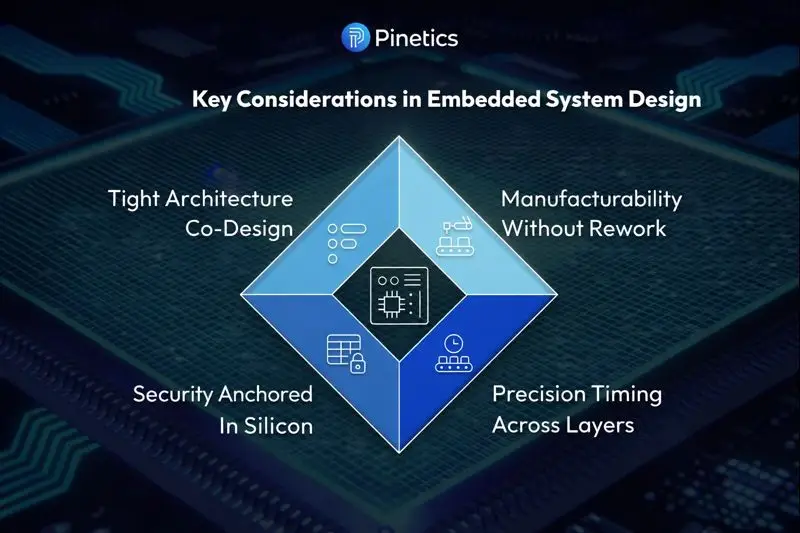
The foundation of reliable embedded systems is hardware and software engineered as one tightly coupled system rather than as layers stacked on each other. Silicon choice, firmware behaviour, timing, security, manufacturability and scale are decided together from day one, because an embedded product lives in the physical world of voltage, temperature, interference and real-time deadlines, and fails as a whole.
If you are choosing an embedded engineering partner now, four questions test whether hardware and software will be co-designed rather than integrated at the end: whether a firmware architect sits in the silicon evaluation; whether the latency budget is modelled across ADC, DMA, bus, RTOS and interrupt layers before the board exists; where the root of trust and the key storage are decided; and which production tolerances the firmware is written to survive. A proposal that answers all four in writing is describing a system, not a stack.
In embedded systems, hardware and software are not independent layers stacked on top of each other. They are a single, tightly coupled system that must be engineered as one, or they will fail together.
Unlike traditional software systems, embedded products live in the physical world. They interact with voltage fluctuations, temperature extremes, timing constraints, electromagnetic interference, and real-time human or machine behaviour. In this environment, success is not determined by clean interfaces alone. It is determined by how deeply hardware and software decisions are aligned from day one.
At the heart of embedded systems development lies a simple truth: integration is not enough. What is required is co-creation, a design philosophy where hardware architecture, firmware behaviour, and system constraints are defined together as one unified system.
This mindset is what separates scalable, production-ready embedded products from fragile prototypes that collapse under real-world conditions.
Why is hardware and software co-design non-negotiable in embedded systems?
Hardware and software co-design is non-negotiable in embedded systems because the microcontroller or SoC is a system-defining architectural choice, not a procurement decision: it fixes clock domains, memory latencies, interrupt nesting, DMA bandwidth, real-time determinism boundaries and power modes, and every one of those constrains the firmware. Firmware architects belong in silicon evaluation, not at board bring-up.
One of the most common failures in embedded projects begins with a seemingly harmless assumption: that hardware selection can be finalised before software architecture is fully defined.
Microcontroller or SoC selection is not a procurement decision. It is a system-defining architectural choice.
The selected silicon determines:
- Clock domains and frequency scaling options
- Memory hierarchies and access latencies
- Interrupt nesting behaviour
- DMA bandwidth and contention
- Real-time determinism boundaries
- Power modes and wake-up latencies
Each of these factors directly constrains firmware behaviour.
Firmware is not just application logic. It governs:
- Power state transitions
- Bus arbitration and peripheral access
- Fault detection and recovery
- Watchdog strategy
- Device identity and security enforcement
Every clock cycle matters. A mismatch between hardware capabilities and firmware expectations results in timing drift, race conditions, unstable peripherals, or unexplained system resets.
Effective hardware design and development, therefore, cannot proceed in isolation. Firmware architects must be involved when silicon is evaluated, not after boards are already fabricated.
Whether a firmware architect was in the room is hard to verify after the fact; a signed document with a date on it is not. On a Pinetics programme the architecture gate has published exit criteria, and one of them is a signed hardware/software interface control document. Architecture is done when the criteria are signed, not when the diagram looks right. The check to run on your own programme is to ask for that document by name and read its date against the date the board was released to fabrication.
Why is precision timing a system property in embedded systems?
Precision timing is a system property in embedded systems because a latency budget of a millisecond or less is spent across layers at once: ADC sampling, DMA transfer windows, bus arbitration, RTOS scheduling and interrupt service routines. A small mismatch in any one passes early testing and fails intermittently under load, so timing has to be modelled, not assumed.
Embedded systems often operate under strict latency budgets, sometimes measured in microseconds or milliseconds. In these environments, even small mismatches between layers can cascade into system-wide failures.
Consider a system with a 1 ms response requirement:
- ADC sampling timing
- DMA transfer windows
- Bus arbitration latency
- RTOS task scheduling
- Interrupt service routines
If any one of these is slightly misaligned, the system may appear functional during early testing but fail intermittently under load.
Timing in embedded systems must be modelled, not assumed.
Cross-domain synchronisation between analogue sampling, digital processing, and communication requires mathematical analysis. Firmware developers must understand how hardware timers behave under temperature drift. Hardware designers must understand how RTOS scheduling interacts with interrupt latency and cache behaviour.
This is where mature embedded product development services differentiate themselves. Timing is treated as a first-class design parameter, not an implementation detail discovered late in validation.
How a hardware timer behaves as temperature changes can be observed rather than assumed. IEC 60068-2-14 “provides tests with specified ambient temperature changes to analyse their impacts on specimens”, so a timing model that has never been checked against the timer’s behaviour across that test’s temperature range is a model of the bench, not of the product. Ask for the timing budget as a table with a worst-case column, and ask at what temperature the worst case was measured.
Why must embedded security be anchored in silicon?
Embedded security must be anchored in silicon because a software-only design leaks keys and accepts replaced firmware in the field. Secure boot, cryptographic key storage, device identity and runtime authentication rest on hardware features such as a root of trust, secure key storage, a trusted execution environment, memory protection units and hardware random number generators. Firmware extends those trust boundaries.
Security failures in embedded products are rarely caused by a single vulnerability. They are usually the result of security being treated as a software-only concern.
In secure embedded systems, trust begins with hardware.
Secure boot, cryptographic key storage, device identity, and runtime authentication must be rooted in silicon features such as:
- Hardware root of trust
- Secure key storage
- Trusted execution environments
- Memory protection units
- Hardware-backed random number generators
Firmware plays a critical role, but only as an extension of hardware-enforced trust boundaries.
If security is treated as an API-layer feature added after hardware decisions are finalised, it becomes fragile. Keys leak, firmware can be replaced, and devices become untrustworthy in the field.
Strong firmware development services embed security logic directly into the hardware abstraction layer. Power-on behaviour, boot sequencing, firmware updates, and runtime validation are all designed together with hardware capabilities in mind.
In embedded systems, security is not something you add. It is something you architect.
Secure boot and firmware recovery have a framing publication of their own. NIST SP 800-193, Platform Firmware Resiliency Guidelines, “provides technical guidelines and recommendations supporting resiliency of platform firmware and data against potentially destructive attacks” and defines the platform as “a collection of fundamental hardware and firmware components needed to boot and operate a system”. It is a US federal guideline rather than a standard, and it frames firmware resiliency as protection, detection and recovery rather than as three separate features. On a Pinetics programme that architecture is signed, not assumed: a signed cybersecurity architecture decision is one of the architecture gate’s published exit criteria. The check to run is to ask which document records where the root of trust and the key storage live, who signed it and on what date.
How do you design an embedded system for manufacturability without rework?
You design an embedded system for manufacturability without rework by anticipating production reality instead of assuming the lab bench: component tolerances, temperature drift, voltage noise, ageing, assembly variation and EMI and ESD exposure. Firmware operates at worst-case boundaries, with calibrated ADCs, timing margins and resilient start-up, and hardware is chosen and laid out for predictable behaviour across variance.
A prototype that works on a lab bench is not a product.
Manufactured embedded systems must tolerate:
- Component tolerances
- Temperature drift
- Voltage noise
- Ageing effects
- Assembly variation
- EMI and ESD exposure
Hardware and firmware must anticipate these realities.
Firmware should never assume ideal conditions. It must be designed to operate safely and predictably across worst-case boundaries, not best-case scenarios.
Examples include:
- ADC calibration routines that account for temperature variation
- Timing margins that tolerate clock drift
- Startup sequences resilient to slow power ramps
- Peripheral initialisation that handles transient faults
- Communication stacks are tolerant of noise and retries
From a hardware design and development perspective, this means selecting components and layouts that support predictable behaviour across production variance. From a firmware perspective, it means designing defensive logic that expects hardware imperfections.
Testing against nominal conditions is insufficient. Survival depends on testing against extremes.
Component tolerances, temperature drift, voltage noise, ageing, assembly variation and EMI and ESD exposure are each addressed by a different design control. Two of the six have a published IEC test method a buyer can ask to see the product run against: IEC 60068-2-14 for change of temperature; IEC 61000-4-2 and IEC 61000-4-3 for electrostatic discharge and radiated radio-frequency immunity.
Six production realities a manufactured embedded system must tolerate, the design control for each and the check to run
| Production reality | Design control | Check to run |
|---|---|---|
| Component tolerances | Worst-case circuit analysis, part selection | Tolerance stack-up on the sensing and timing paths |
| Temperature drift | Calibration routines, thermal design | Behaviour across IEC 60068-2-14 temperature change |
| Voltage noise | Supply filtering, brown-out handling, margins | Start-up and operation on a slow or dirty rail |
| Ageing effects | Derating, firmware that tolerates drift | Which parameters are re-calibrated in service |
| Assembly variation | Design for manufacture, design rule check, test points | Manufacturability review record before release |
| EMI and ESD exposure | Layout, filtering, protection devices | Immunity to IEC 61000-4-3 and IEC 61000-4-2 tests |
The manufacturability review is the control a buyer can inspect before any test is run. On a mains-powered patient-warming device programme, Pinetics’ reviews check manufacturability, not just correctness: via size and tenting, test-point footprints, board dimensions in millimetres and a clean design rule check before release are all standing gate items. None of those is a tolerance a chamber will find; each is a decision that, left to the fabricator, becomes a rework. The check to run on your own programme is to ask for the review record of the last board released and see whether manufacturability items sit on it as gate items or as remarks.
Our post on why embedded systems fail in the field works through the environmental test methods for the extremes, and our post on EMI and EMC design for MedTech devices covers the interference and discharge tests in depth.
Why is integration the wrong goal for embedded systems?
Integration is the wrong goal for embedded systems because it treats hardware and software as two independently designed things to be connected at the end, which is where embedded projects fail. The right goal is co-creation: hardware architecture validated against firmware timing models, state machines designed for electrical behaviour, power budgets owned jointly and tests that validate the system.
Many teams talk about hardware-software integration as a phase at the end of development. This framing is misleading.
Integration implies that two independently designed systems are being connected. In embedded systems, this approach almost always fails.
The correct goal is co-creation.
Co-creation means:
- Hardware architecture decisions are validated against firmware timing models.
- Firmware state machines are designed with electrical behaviour in mind
- Power budgets are jointly owned by hardware and software teams.
- Test strategies validate the system, not isolated components
Every architectural decision affects every other layer.
This co-creative approach is the foundation of reliable embedded systems development.
Co-creation is a mindset until each of its four practices leaves a document behind, and then it is a gate.
Four co-creation practices, the artefact each leaves behind and the check to run
| Co-creation practice | Artefact it leaves behind | Check to run |
|---|---|---|
| Architecture validated against firmware timing models | Timing budget with worst-case column | Who ran the model, and against which silicon |
| State machines designed for electrical behaviour | State machine with electrical entry conditions | What each state assumes about the rails |
| Power budgets jointly owned | Accepted power budget, worst-case envelope | Whether radio and motor peaks are in it |
| Tests validate the system | System test plan, not module tests | Which tests run the whole unit under load |
A power budget and an interface control document are artefacts any team can produce. On a Pinetics programme both sit inside the published exit criteria of the architecture gate: an accepted power budget with worst-case envelope sizing and a signed hardware/software interface control document. That is the difference between saying power budgets are jointly owned and being able to show the accepted budget.
Test strategy answers to the same standard. A system test plan that exercises the assembled unit under its real loads, or a hardware-in-the-loop rig that runs the firmware against a simulated version of the machine it controls, is something a buyer can ask to see; a stack of module test reports is not the same evidence. Our page on how an electronic product development programme is staged and gated sets out where the architecture gate sits.
Why does scaling embedded products require system thinking?
Scaling embedded products requires system thinking because scale brings higher duty cycles, more diverse environments, longer lifetimes, stricter regulatory scrutiny and years of firmware updates, and a prototype never designed as a whole fails there. Scalable embedded systems have clear hardware-software contracts, deterministic timing, hardware-rooted security, firmware that anticipates degradation and validation that mirrors real use.
Fragile prototypes often fail when scaled, not because the idea was flawed, but because the system was never designed as a whole.
As products scale, they encounter:
- Higher duty cycles
- More diverse environments
- Longer operational lifetimes
- Stricter regulatory scrutiny
- Firmware updates over the years
Only systems engineered holistically can survive this transition.
Scalable embedded products are defined by:
- Clear hardware-software contracts
- Deterministic timing behaviour
- Hardware-rooted security models
- Firmware that anticipates degradation
- Validation strategies that mirror real-world use
This level of maturity does not emerge accidentally. It is the result of disciplined embedded product development services that treat the system as one organism, not a collection of parts.
In medical devices, stricter regulatory scrutiny has a named shape. IEC 62304 “defines the life cycle requirements for medical device software”, which puts the firmware updates over the years inside a defined software life cycle rather than outside one. A hardware-software contract written at the start is what keeps the later releases consistent with the first; the question to put to a supplier is whether the interface control document is under version control alongside the firmware, or was a one-off drawing.
What does getting hardware-software co-design wrong cost?
Getting hardware-software co-design wrong in embedded systems costs late redesigns, missed performance targets, unexplained field failures, security vulnerabilities, manufacturing delays, excess power consumption and unreliable updates, and most are impossible to fix without significant rework. Teams that co-design early ship products that behave predictably under stress, scale to production, evolve their firmware and stay reliable for years.
When hardware and software are designed separately, the consequences are predictable:
- Late-stage redesigns
- Missed performance targets
- Unexplained field failures
- Security vulnerabilities
- Manufacturing delays
- Excessive power consumption
- Unreliable updates
These issues are expensive to fix and often impossible to correct without significant rework.
By contrast, teams that invest early in hardware-software co-design deliver products that:
- Behave predictably under stress
- Scale smoothly from prototype to production
- Support long-term firmware evolution
- Meet regulatory and security requirements
- Maintain reliability across years of operation
Bridging hardware and software in embedded systems is not about better integration practices. It is about a fundamentally different mindset.
Embedded systems are not layered with abstractions; they are unified, physical systems. Every architectural decision, every layout constraint, every interrupt handler, and every line of firmware must be engineered as part of a single, coherent whole.
This co-creation mindset sets scalable, production-ready embedded products apart from fragile prototypes that lack real-world robustness.
At Pinetics, this philosophy guides everything we build. Our expertise spans embedded systems development, hardware design and development, firmware development services and embedded product development services, enabling us to engineer embedded products as complete systems, not disconnected components. We partner with organisations to design hardware and software together from the outset, ensuring reliability, security, manufacturability and long-term scalability: the hardware/software interface control document and the cybersecurity architecture decision signed at the architecture gate, the power budget and the thermal feasibility study accepted there, and manufacturability checked as a gate item before a board is released. Behind that are 100,000+ engineering hours and a leadership team with 20+ years of experience, and the work runs inside the customer’s quality system rather than under a certification of our own.
If your embedded product must perform in the real world, not just the lab, Pinetics is ready to help you engineer it right.
Sanjay Barewar, Director, Co-Founder and Global Chief Delivery Officer, Pinetics. 22+ years in electronic product development. BE Electrical, Pune University. LinkedIn